Arduino Project 028A - Basic Stepper Control (Bipolar)
In this very simple project, you will connect up a stepper motor and then get the Arduino to control it in different directions and at different speeds for a set number of steps. You will study different types of stepper motor, bipolar 4 wires and 5 wires, unipolar 6 wires.
Bipolar stepper motors are generally able to produce more torque than unipolar stepper motors, and are more efficient.
However, they are more complicated to drive (="operate"). The main difference between the two types of stepper motors has to do with the way that the wire winding is constructed.
Project 28 Basic Stepper Control (Bipolar)
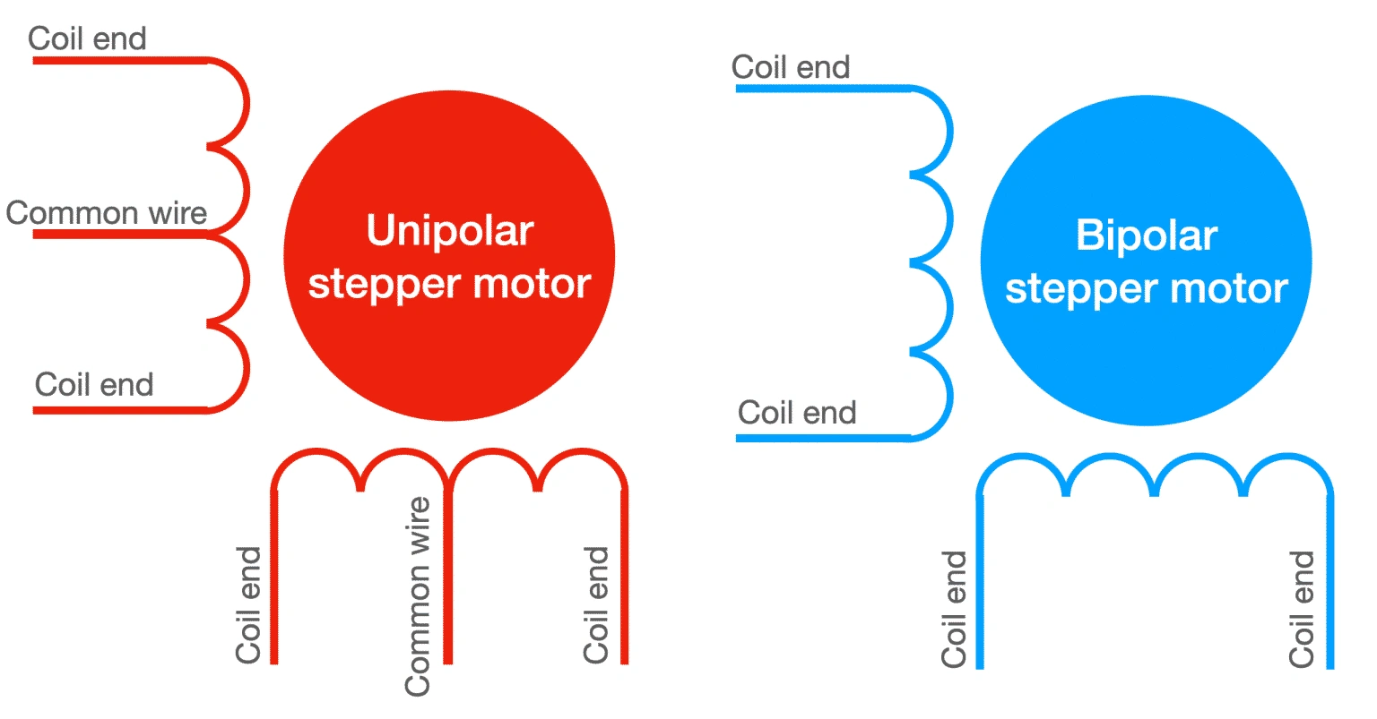
Here's a simplified depiction of the wire winding for the two types of stepper motors.
The unipolar motor has a central common tap per phase. The bipolar motor does not.
In the schematic above, you can see a bipolar stepper motor and a unipolar stepper motor with two phases each.
A wire winding arrangement is refered to as a "phase"
The unipolar stepper motors, has one winding per phase, with a center tap. This allows the controlling circuit to operate the motor with current that flows always in the same direction. Therefore, there is no need to generate reverse current. Each time the phase is activated, only half of its coil is energized.
The bipolar stepper motor also has a single winding per phase. However, there is no center tap. This means that when the phase is activated, the entire coil is energized. The result is that the bipolar motor is able to produce much more torque compared to the unipolar motor. But, there is a cost: the controlling circuit must be able to generate current that can move both ways through the coil, i.e. "regular" current and "reverse" current. As a result, the controlling circuit for a bipolar stepper motor is more complicated then that of a unipolar stepper motor.
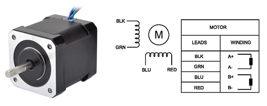
Bipolar motors have multiple (at least two) independent windings. A wire comes out of each of the winding's ends, so you get two wires per winding.
Unipolar motors may also have multiple (more than two) windings. However, in addition to the ends of each winding are connected to wires, the middle attaches to a third wire.
The absence of this third (common) wire means that bipolar motors are slightly easier to make.
Stepper motor drivers
When it comes to driving stepper motors, the simpler bipolar motor requires a more complex driver; this is because, to precisely control its motion, we need to be able to drive current in each winding in both directions.
On the other hand, in a unipolar motor, we can get away with a current that flows only in a single direction; this means that the driver electronics can be made simpler. The trade-off is that we use only half of each winding coil at a given time, and this translates to lower torque and efficiency.
However today, with easy access to motor drivers like H-bridges, it is easy to drive bipolar motors with alternating current. Unipolar motors advantage of not needing the reverse current is not a big deal anymore so it is possible to get all of their operational advantages with minimal cost.
To drive a stepper motor with your Arduino, you can use these drivers (This project includes some common examples):
A4988, can control one bipolar motor with up to 2A of current per coil.
DRV8825, can control one bipolar motor with up to 2.2A of current per coil.
L298N, a classic driver, can control one bipolar motor with up to 2A of current per coil.
TB6600, can control one large bipolar motor with up to 4.5A of current per coil.
ULN2003, can control one small 5V unipolar stepper motor.
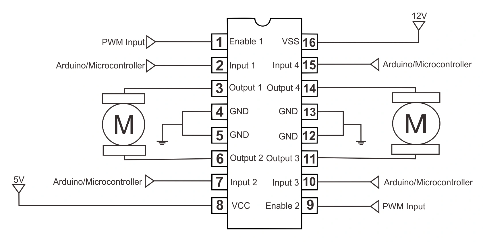
L293D IC is known as a motor driver. It is a low voltage operating device like other ICs. The other ICs could have the same functions like L293d but they cannot provide the high voltage to the motor. L293d provides the continuous bidirectional Direct Current to the Motor. The Polarity of current can change at any time without affecting the whole IC or any other device in the circuit. L293d has an internal H-bridge installed for two motors.
H-Bridge is an electrical circuit that enables the load in a bidirectional way. L293d bridge is controlled by external low voltage signals. It may be small in size, but its power output capacity is higher than our expectation. It could control any DC motor speed and direction with a voltage range of 4.5 – 36 Volts. Its diodes also save the controlling device and IC from back EMF. To control the max 600mA amount of current an internal “Darlington transistor sink” installed in it, which could be used to control a large amount of current by providing a small amount of current. It has also internal “pseudo-Darlington source” which amplifies the input signal to control the high voltage DC motor without any interception.
Project 28 Components
Arduino UNO 1 EA
Stepper Motor 1 EA
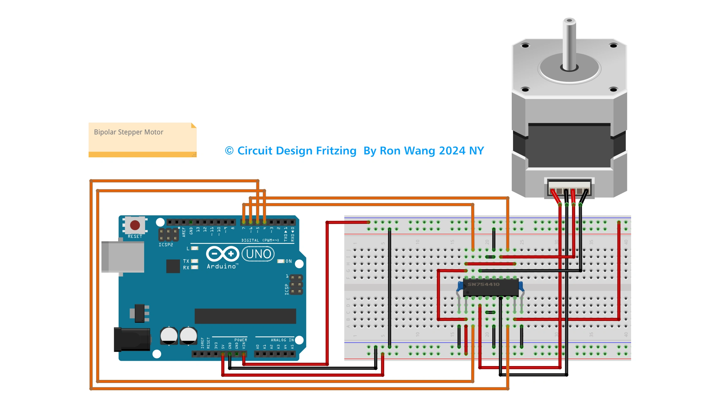
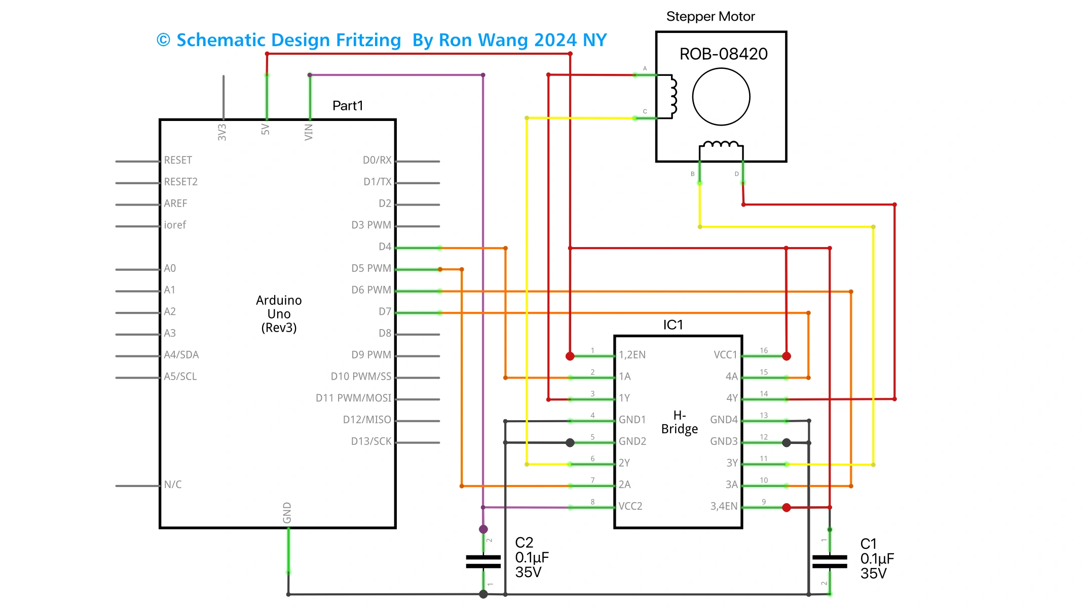
IC L293D / SN754410 1 EA
Ceramic Capacitor 0.01uF 2 EA
Dupon Wire ~
Bipolar Stepper Motor
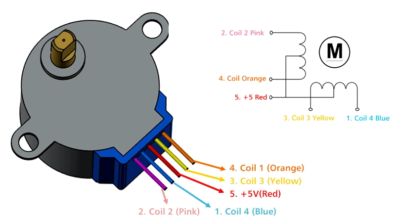
Bipolar stepper motor have the 4 wires and 5 wires . 4wires connect the (L293D A connect to pin3 and pin6,another connect to pin 11 and pin 14 ) . 5 wires connect the the red cable to 5~12V
/* Coding Ron Wang
   Nov.18th 2024
   Autaba support for coding hardware
   Project 28  Basic Stepper Control
 */

#include <Stepper.h>
// steps value is 360 / degree angle of motor
#define STEPS 200
// create a stepper object on pins 4, 5, 6 and 7
Stepper stepper(STEPS, 4, 5, 6, 7);
void setup()
{
}
void loop()
{
 stepper.setSpeed(60);
 stepper.step(200);
 delay(100);
 stepper.setSpeed(20);
 stepper.step(-50);
 delay(100);
} 版权声明:本文为原创文章,版权归donstudio所有,欢迎分享本文,转载请保留出处!


