Modeling and Evaluating of the Stewart Platform
Abstract
This paper presents an algorithm for solving forward kinematics problem of the Stewart Platform and an application for modeling of the Stewart Platform's motions. The developed application is able to solve forward kinematics problem in given accuracy; to calculate curve of the tool positioned on the mobile platform; tocalculate possible deviation of the tool from a nominal position if lengths of the legs can vary in given range; to detect crossing ofthe legs during motions of the mobile platform. The movements of the Stewart Platform can be specified though explicit laws of motions or trough spline-interpolation based on given nodes. The computational engine of the program is constructed on neweffective methods and algorithms.
Keywords: CAD; CAE; Kinematics; Stewart Platform; Parallel manipulators.
1. INTRODUCTION
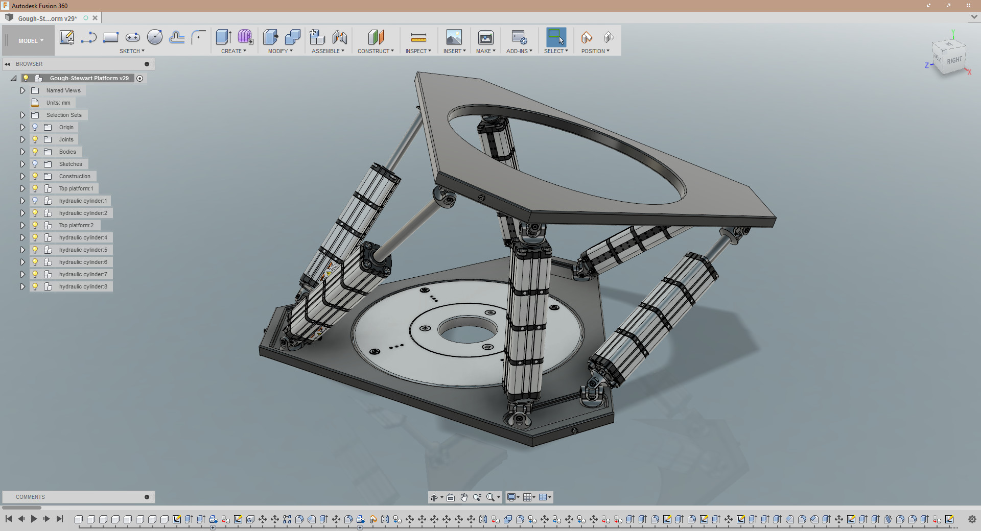
The Stewart Platform mechanism, originally suggested by D.Stewart in [1], is a parallel kinematic structure that can be used as a basis for controlled motion with 6 degrees of freedom (dof), such as manufacturing processes and precise manipulative tasks.The mechanism itself consists of a stationary platform (base platform, the base) and mobile platform that are connected via six legs (struts) mounted on universal joints. The legs have an in-built mechanism that allows changing the length of each individual leg.
The desired position and orientation of the mobile platform is achieved by combining the lengths of the six legs, transforming the six transitional dof into three positional (displacement vector) and three orientational ones (angles of rotation of a rigid body in space). The lengths of the legs cannot, of course, be changed independently, but only in such a fashion that the platform construction allows.
The figure 1 shows general structure of the Stewart Platform.
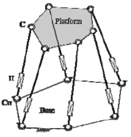
Figure 1: The Stewart Platform
The advantages of the Stewart Platform are 6 degrees of freedom, as already said, and a split-hair accuracy of mobile platform positioning. This makes the Stewart Platform structures wide usable in robot-building related infrastructures.
For example, such parallel kinematic structure is used in National Advanced Driving Simulator (NADS), see figure 2.
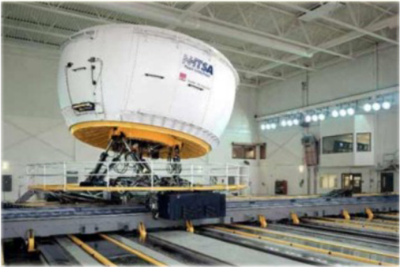
Figure 2: National Advanced Driving Simulator (NADS)
2. PREVIOUS WORKS
A design of the Stewart Platform requires especially CAD systems, since it has very sophisticated geometry and a quality of its modeling defines a quality of final product, cost of its creation and future exploitation.
One of the most celebrated CAE-products, which provide calculation of different kinematic structures, is MSD.Dynamic Designer delivered by MacNeal-Schwendler Corporation (MSC)[2]. This product is for kinematic and dynamic analysis of mechanisms and its 3D motions. A number of systems where the MSD.Dynamic Designer product used in constantly increases and now it includes: Autodesk Mechanical Desktop, AutoCAD/Me-chanical, Autodesk Inventor, SolidWorks, SolidEdge, CATIA, etc.
Listed above software products are able to solve different problems of dynamics. But kinematic problems are mainly reduced to visualization of possible motions and to detection of crossings. It is not a little, but not enough for the Stewart Platform. First of all, it is not enough, because a trajectory of mobile platform is not the only thing needed to be calculated.
Also it is quite useful to know possible deflections from nominal trajectory, which naturally always occurs if lengths of the legs vary in some range (actually real legs never have exactly equal lengths we set)
3. FORWARD KINEMATICS PROBLEM AND SOLUTION ALGORITHM
The forward kinematics problem (the direct position kinematics problem) enjoyed the central status in the research on the Stewart Platform. The problem is to determine the position and orientation of the platform depending on given six leg lengths.
Geometrically, it is equivalent to the problem of placing a rigid body such that six of its given points lie on six given spheres.
The forward kinematics problem can be represented by the following system of kinematic equations:
| t+ R*Pi - bi |2 = Li2, i=1,...,6 ( 1 )
where t – the translation vector of platform frame origin; bi H Pi – the joint points on the base and on the platform respectively; R – the orthogonal rotation matrix; Li – given leg lengths between bi and Pi. The unknowns of this system of six simultaneous equations are three components of the vector t and three rotation angles, which determine the matrix R.
• not found a way of platform restructuring which gives minimum of unknown quantities in simultaneous equation
• when using platform restructuring and decomposition, the existent approaches do not take into account geometry of possible motions in kinematic chains
• most if not all of the approaches do not guarantee that the solution will be correctly found, if new position of the platform is quite distant from the previous one
The main advantage of the zero-order Stewart Platform is that it can be solved in an explicit way using just the following formula:
P2 = b2 + L2* e1 , e1= f ( u1,e21, cosα1 , cosα2, δ1)
P3 = p1 + Lp1p2* e2 , e1= f ( u2, e13 , cosβ1 , cosβ2, δ2) ( 2 )
,where u2 = ( p2-p1)/Lp1p2 ; δ1 = sign ( e1*[u1*e21] ) ; δ2 = sign ( e2*[u2*e13] ) ; f – Chase's function calculating third ort from two given ones in the following way:
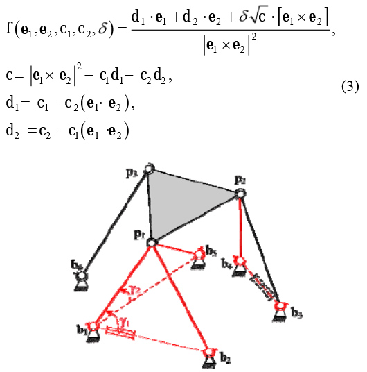
Figure 3: The zero-order Stewart Platform
Saying "order" here, we mean a number of non-linear closedness equations in the forward kinematics problem. Since the platform above has no non-linear equations, it is called "zero-order".
Let us detail the approach. The method of the zero-order Stewart Platform is applicable for each platform from 6-N class. For more information on classification, please see [4]. In order to solve forward kinematics problem for some 6-N platform, the method reduces the given platform to zero-order one and solves a sequence of forward kinematics problems for the zero-order platform (note that such problem can be solved in the explicit way).
4. THE STEWART PLATFORM 6-3 SPS
Restructuring of the 6-3 SPS platform to zero-order case, we remove (in imagination) the leg b5p3 and add fictious leg b5p1
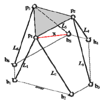
Figure 4: Restructuring of the 6-3 SPS platform
| p3 ( L1,...,L4,x, L6) - b5|2 = L52 (4)
4.2 Computational solution:
For the purpose of computational solution, expression (4) can be taken in the following way:
F(x) = | p3 ( L1,...,L4,x, L6) - b5|2 - L52 = 0 (5)
The iterative method based on Newton's one has been built to achieve rapid convergence. This method uses analytical calculation of first-order derivative F'( X (k)), where k – number of iteration. The calculation of first-order derivative expression takes into account geometry of possible instantaneous motions in the zero-order platform which happen when length of the fictitious leg is being changed. Due to this fact, the forward kinematic problem can be solved as well even if being calculated position is distant from the previous one.
5. THE STEWART PLATFORM 6-6 SPS
5.1 Restructuring to the zero-order Stewart Platform
The 6-6 SPS Stewart Platform is restructured by the following operations:
• removing of the leg b2p2 ; addition of fictitious leg b2p1 instead;
• removing of the leg b4p4 ; addition of fictitious leg b4p3 instead;
• removing of the leg b5p5 ; addition of fictitious leg b5p1 instead;
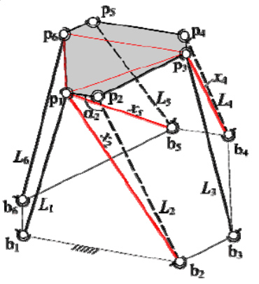
Figure 5: Restructuring of the 6-6 SPS platform
As result we have the following equations for this platform:
|pi(L1,x2,L3,x4,x5,L6)-bi|2 = Li2, i=2,4,5 ( 6 )
5.2 Computational solution:
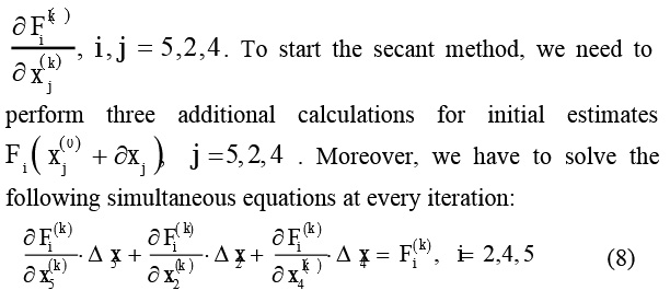
Fi ( x2,x4,x5 ) = |pi(L1,x2,L3,x4,x5,L6)-bi|2 - Li = 0 ( 7 )
where i= 2,4,5
In this case we have to know nine partial derivatives
6. THE APPLICATION
The application has been developed which uses described above method for solving the forward kinematics problem of the Stewart Platform.
The user can design any platform from 6-N class. Firstly, one should create the Stewart Platform and chose its type, position of the base and origin position of the mobile platform.
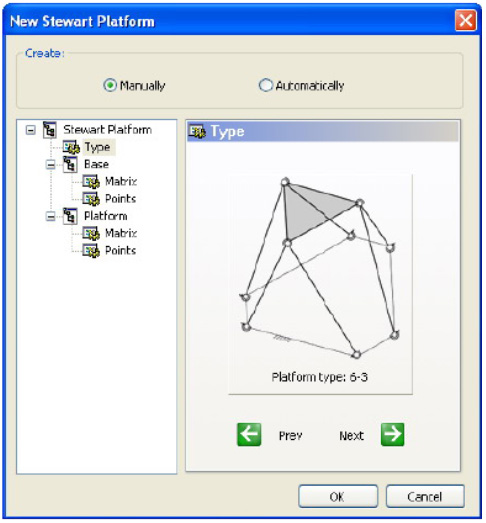
Figure 6: New Stewart Platform dialog
Then the user can specify different properties of the Stewart Platform such as:
• expressions of mobile platform motions;
• properties of the forward kinematic platform algorithm;
• properties of calculating possible deviation of the tool from nominal position;
• properties of the Stewart Platform appearance on the scene;
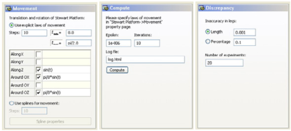
Figure 6: Properties of the Stewart Platform
The movements of the Stewart Platform can be specified though explicit laws of motions or trough spline-interpolation based on given nodes.
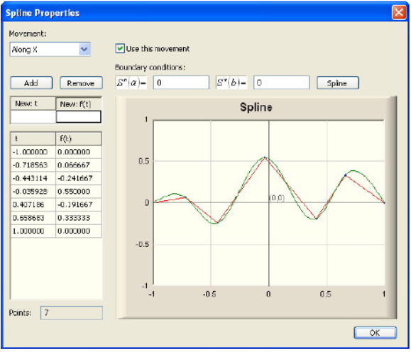
Figure 7: Spline-interpolation
When the Stewart Platform motions have been calculated, the application can visualize them on 3D scene.
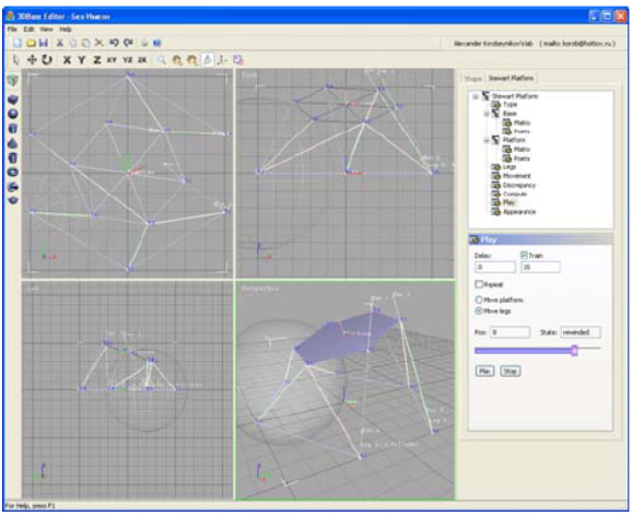
Figure 7: Main window
The application is able also to calculate possible deviation of the tool from nominal position if lengths of the legs can vary in given range. To do this the program performs a sequence of statistical experiments varying the lengths of legs and analyzing how such changes influence on a position of the tool based on the mobile platform.
The program can also detect crossing of the legs during motions of the mobile platform.7. CONCLUSION
The approach for the forward kinematics problem of the Stewart Platform parallel manipulator named method of the zero-order Stewart Platform has been successfully improved, implemented and tested. This method uses effective restructuring of a given Stewart Platform to the zero-order case. Moreover, the method of the zero-order Stewart Platform uses such a number of unknown variables which is one less than suggested in article [8]. An advantage of this method is also that in problem solving it uses Newton's method instead of searching methods as suggested in papers [11] and [12].
Experiments prove that the suggested algorithm has second order of convergence and is applicable in cases when desired position is quite distant from an previous one.
Using the approach, we have developed an application which is able:
• to solve forward kinematics problem in given accuracy;
• to calculate curve of the tool positioned on the mobile platform;
• to calculate possible deviation of the tool from nominal position if lengths of the legs vary in given range;
• to visual all the operations through friendly user interface using MFC library and OpenGL standard.
8. REFERENCES
[1] Stewart, D.A. – Platform with six degrees of freedom// Proc. Inst. Mech. Engr., Vol.180, Part I, No. 15, 1965/1966, pp. 371-386.
[2] MacNeal-Schwendler Corporation (MSC) – MSC.Dynamic Designer (http://www.dynamicdesignermotion.com)
[3] Dasgupta B, Mruthyunjaya T.S. – The Stewart platform manipulator: a review// Mechanism and Machine Theory, 35 (1):Jan 2000, pp. 15-40.
[4] Турлапов В.Е. – Решение задач кинематики дляплатформы Стюарта методом группы нулевого порядка //Электрон. ж. "Прикладная геометрия". Вып.4. №5. МАИ.март 2002г. C.23-40. (http://www.mai.ru/~apg/)
[5] McCallion, H., Truong, P.D. The Analysis of a Six-Degree-of-Freedom Workstation for Mechanized Assembly// Proc. of The Fifth World Congress on Theory of Machines and Mechanisms, Monreal, Canada, jul 8-13 1979, pp.611-616.
[6] Fichter, E.F. A Stewart Platform-Based Manipulator:General Theory and Practical Construction// Int. J. Robot. Res.,1986, Vol. 5, No. 2, pp. 157-182
[7] Griffis, M., Duffi, J. A Forward Displacement Analysis of a Class of Stewart Platform// J. of Robotic Systems, Vol. 6, No. 6,1989, pp. 703-720
[8] Innocenti C., Parenti-Castelli V. Forward kinematics of the general 6-6 fully parallel mechanism – an exhaustive numerical approach via a mono-dimensional-search algorithm//Journal of Mechanical Design. 115 (4): dec 1993, pp. 932-937
[9] Hunt, K.J. Structural Kinematics of In-Parallel-Actuated Robot-Arms// ASME Journal of Mechanisms, Transmissions and Automation in Design, Vol. 105, 1983, pp. 705-712
[10] Турлапов В.Е. Явные решения задачи о положениях на классе одноконтурных групп пространственных рычажных механизмов// Проблемы машиностроения и надежностимашин. 1997. №3. С.87-96
[11] Глазунов В.А., Колискор А.Ш., Чернов В.Ф. и др. Крешению прямой задачи о положениях L-координатныхмеханизмов // Проблемы машиностроения и надежностимашин. 1991. №2. С.100-105.
[12] Глазунов В.А., Колискор А.Ш., Крайнев А.Ф.Пространственные механизмы параллельной структуры. –М.:Наука, 1991. 96с.
About the authors
Alexander V. Korobeynikov, Vadim E. Turlapov Department of Computational Mathematics and Cybernetics,
Nizhny Novgorod State University after N.I.Lobachevski,Nizhny Novgorod, Russia korob@hotbox.ru, vadim.turlapov@cs.vmk.unn.ru
Vadim E. Turlapov – Doctor of Technical Science, professor of Nizhny Novgorod State University after N.I.Lobachevski, Nizhny Novgorod, Russia.
E-mail: vadim.turlapov@cs.vmk.unn.ru
Alexander V. Korobeynikov – student of Nizhny Novgorod State University after N.I.Lobachevski, Nizhny Novgorod, Russia.
E-mail: korob@hotbox.ru
International Conference Graphicon 2005, Novosibirsk Akademgorodok, Russia, http://www.graphicon.ru/
版权声明:本文为原创文章,版权归donstudio所有,欢迎分享本文,转载请保留出处!


